|
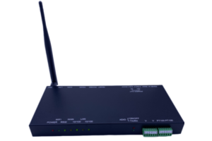
TE572A hardware deion

Figure 1
Figure 2 shows the backplane of the LTE572A, and the names of each part are as follows:

圖2
LTE572A functions

Figure 3

Figure 4
Pin2 : D+
Pin8: D-
The position of the feet is shown in Figure 5 Since there is no GND signal here, if the digital meter or the device connected to this port does not use the locally provided 12V voltage output as the power supply, then it is necessary to consider connecting this device to the local GND signal, otherwise RS485 communication may be unstable Both 12V and 5V voltage outputs of this machine can provide GND signals In addition, the internal ADIO already uses Modbus address 1, so the digital meter Modbus is connected to this port The address should be set to 2

Figure 5
1~5 seconds : Turn it back on with the existing settings
10~20 seconds : Turn it back on with factory settings, the original settings will be cleared after opening, login information is shown on label.
- Deion of the TE572A panel and backplane
- Power LED
- WiFi (802.11ah) indicator
- Wireless signal strength indicator
- WAN connection indicator
- WAN connection speed indicator
- LAN connection indicator
- LAN connection speed indicator
- ADIO module power indicator
- ADIO module communication indicator
- ADIO module voltage measurement input connector
- ADIO module temperature sensor (PT100) input connector
Figure 1
Figure 2 shows the backplane of the LTE572A, and the names of each part are as follows:
- RS485 port (connected to digital power meter).
- 12V voltage output (connected to digital power meter).
- 5V voltage output
- RESET button.
- 12V Power Supply Input
- RS485 port (reserved).
- WAN port
- LAN port
- WiFi (802.11ah) antenna connector
圖2
LTE572A functions
- Power LED
- WiFi (802.11ah) indicator
- Wireless signal strength indicator
- WAN connection indicator
- WAN connection speed indicator
- LAN connection indicator
- LAN connection speed indicator
- ADIO module power indicator
- ADIO module communication indicator
- ADIO module voltage measurement input connector
Figure 3
- ADIO module temperature sensor (PT100) input connector
Figure 4
- RS485 port (connected to digital meter).
Pin2 : D+
Pin8: D-
The position of the feet is shown in Figure 5 Since there is no GND signal here, if the digital meter or the device connected to this port does not use the locally provided 12V voltage output as the power supply, then it is necessary to consider connecting this device to the local GND signal, otherwise RS485 communication may be unstable Both 12V and 5V voltage outputs of this machine can provide GND signals In addition, the internal ADIO already uses Modbus address 1, so the digital meter Modbus is connected to this port The address should be set to 2
Figure 5
- 12V voltage output (connected to digital meter).
- 5V voltage output
- RESET button
1~5 seconds : Turn it back on with the existing settings
10~20 seconds : Turn it back on with factory settings, the original settings will be cleared after opening, login information is shown on label.
- 12V mains power import
- RS485 port (reserved).
- WAN port
- LAN port
- WiFi (802.11ah) antenna connector
KEY FEATURES
• Both Access point and station mode
•Security: OPEN, WPA2-PSK(AES), WPA3-OWE,WPA3-SAE
• 902.0 ~ 928.0 MHz Frequency
• +23dBm Transmit Power
WiFi
802.11ah HaLow Supports 1/2/4 MHz bandwidth
INTERFACE
• 2 10/100Mbps LAN port,Auto MDI/MDIX
• 1x12VDC power input, 1x5Vdc power
Output, 1x12Vdc power output to provide
power to external sensor devices.
• External 1 SMA antenna for HaLow.
•1 RS485 port to connect serial device,
Such as power meter or extra AD I/O
device.
Button:
System Reset
LED
Power, wifi status,, 2 10/100 LAN ports, Link/Act,WPS
Embedded system: Yocto Linux Router
Protocol: TCP, FTP, PPTP, HTTP,HTTPS, TFTP, DHCP, NAT, IPSec Pass through, ICMP, IGMP, RIPv2, RIP, OSPF, SNMP, RMON, QoS.
Optional: VPN client or gateway, IPSec client. 4G mobile connection.
Real time clock
• 1 RTC battery to support log data up to 7 days
Others
• Size 24.5cm x 2.5cm x 11.5cm
• Weight 0.5 kg
• Operating temperatures
• Normal operating conditions -30...+75 °C
| TEL:+886-3-5396570FAX:+886-3-5401872ADDRESS:No.20 Lane 526 NiuPu East Road Hsinchu TaiwanEMAIL:peter@lightspeed.com.tw |
| COPYRIGHT © WWW.LIGHTSPEED.COM.TW ALL RIGHTS RESERVED.Design by WELI |
